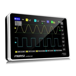
DSO5102P USB Digital Storage Oscilloscope 2Channels 100MHz 1GSa/s
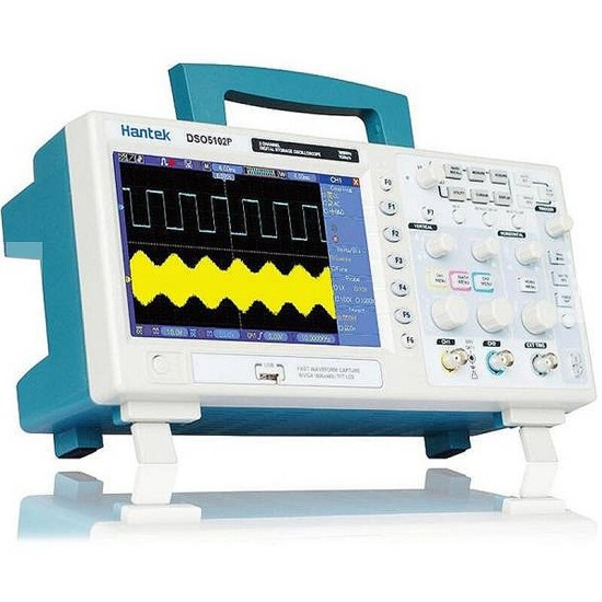
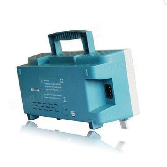
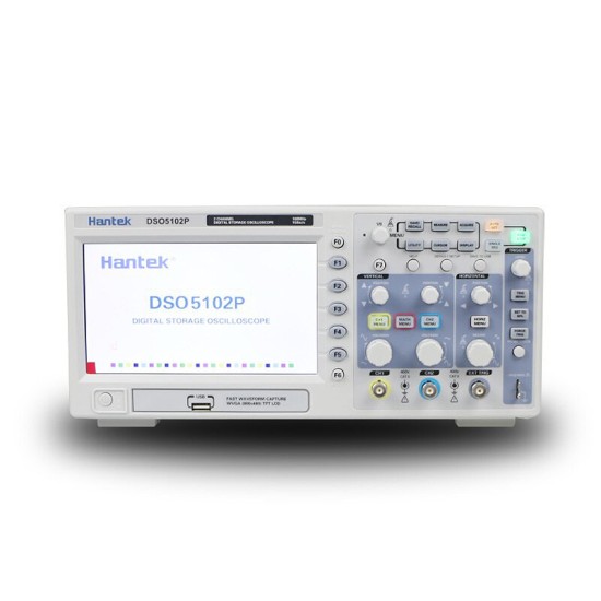
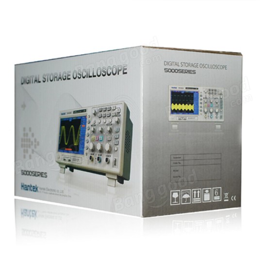


DSO5102P USB Digital Storage Oscilloscope 2Channels 100MHz 1GSa/s
$301.99
Ex Tax: $301.99
- Stock: In Stock
- Model: MZ004748
- SKU: MZ004748
Description:
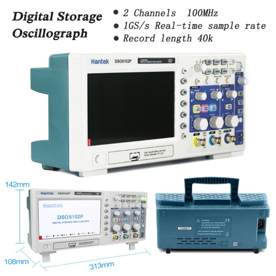
DSO5102P USB Digital Storage Sanda 2 Channel 100MHz 1GSA/S
Features:
100MHz bandwidth
1GSA/S real -time sampling rate
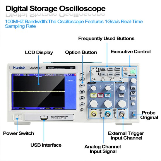
Large (7.0 -inch) color display, WVGA (800x480)
Record length can reach 40K
Triggeon: edge/pulse width/optional video/slope/overtime, etc.
USB host and device connection, standard
Multiple automatic measurement
Four mathematical functions, including FFT standards
Provide PC real -time analysis software
Specification:
| model | DSO5202P | DSO5102P | DSO5072P |
| get | |||
| Sampling Rate | Real -time sampling: 1GS/S Equivalent sampling: 25GS/s | ||
| Acquisition mode | |||
| normal | Only normal data | ||
| Peak detection | High-frequency and random GLITH capture | ||
| average | Waveform Average, Optional 4,8,16,32,64,128 | ||
| enter | |||
| input coupling | AC, DC, Ground | ||
| input resistance | 1MΩ±2% II20pF±3pF | ||
| Probe attenuation | 1X, 10X | ||
| Supported Probe Attenuation Factors | 1X, 10X, 100X, 1000X | ||
| input voltage | CAT I and CAT II: 300VRMS (10×), Installation Category; Category III: 150VRMS (1×); Installation Category II: 13V Peak AC above 100kHz with 20dB/decade derating to 3MHz* and above. For non-sinusoidal waveforms, the peak value must be less than 450V. Offset duration above 300V should be less than 100ms. The RMS signal level (including any DC component removed by AC coupling) must be limited to 300V. If these values are exceeded, the oscilloscope may be damaged. | ||
| horizontal | |||
| Sample rate range | 500MS/s--1GS/s | ||
| Waveform interpolation | (sin x)/x | ||
| record length | 40'K | ||
| SEC/DIV range | 4ns/div to 40s/div | 4ns/div to 40s/div | |
| Sample Rate and Latency Accuracy | ±50ppm (in any time interval ≥1ms) | ||
| location range | 2ns/div to 10ns/div; (-4div xs/div) to 20ms; | 20ns/div to 80us/div; (-8div xs/div) to 40ms; 200us/div to 40s/div; (-8div xs/div) to 400s | |
| Delta time measurement accuracy (full bandwidth) | Single, normal mode: ±(1 sampling interval+100ppm×reading+0.6ns); >16 averages: ±(1 sampling interval+100ppm×reading+0.4ns); sampling interval=s/div ÷ 200 | ||
| vertical | |||
| vertical resolution | 8-bit resolution, all channels sampled simultaneously | ||
| location range | 2mV/div to 200mV/div, ±2V 200mV/div to 5V/div, ±50V | ||
| bandwidth | 100MHz | 100MHz | 70MHz |
| BNC Rise Time (Typical) | 3.5 ns | 3.5 ns | 5ns |
Analog bandwidth in BNC or normal and average mode with probe , DC coupled | 2mV/div to 20mV/div, ±400mV; 50mV/div to 200mV/div, ±2V 500mV/div to 2V/div, ±40V; 5V/div, ±50V | ||
| math | +, -, *, /, Fast Fourier Transform | ||
| Fast Fourier Transform | Windows: Hanning, Flatop, Rectamgular, Bartlett, Blackman; 1024 sample points | ||
| bandwidth limit | 20MHz | ||
| Low frequency response (-3db) | ≤10Hz for BNC | ||
| DC Gain Accuracy | ±3% for Normal or Average acquisition mode, 5V/div to 10mV/div; ±4% for Normal or Average acquisition mode, 5mV/div to 2mV/div | ||
| DC Measurement Accuracy, Average Acquisition Mode | When the vertical displacement is zero and N≥16: ±(3%×reading+0.1div+1mV), only use 10mV/div or greater; when the vertical displacement is not zero and N≥16: ±[3%× (reading + vertical position) + 1% of vertical position + 0.2div]; add 2mV for settings from 2mV/div to 200mV/div; add 50mV for settings from 200mV/div to 5V/div | ||
| Voltage measurement repeatability, average acquisition mode | D 1 incrementVoltage between any two averages of ≥16 waveforms acquired under the same setup and ambient conditions | ||
| trigger system | |||
| trigger type | Edge, Video, Pulse, Slope, Over Time, Alternate | ||
| trigger source | CH1, CH2, EXT, EXT/5, AC line | ||
| trigger mode | Auto, Normal, Single | ||
| Coupling Type | DC, AC, Noise Rejection, High Frequency Rejection, Low Frequency Rejection | ||
| Trigger sensitivity (edge trigger type) | DC(CH1,CH2): 1div from DC to 10MHz; 1.5div from 10MHz to 100MHz; 2div from 100MHz to Full; DC(EXT): 200mV from DC to 100MHz; 350mV from 100MHz to 200MHz; DC(EXT/5): 1V from DC to 100MHz; 1.75V from 100MHz to 200MHz; AC: attenuates signals below 10Hz; HF Reject: attenuates signals above 80kHz; LF Reject: same as DC coupling limit for frequencies above 150kHz; attenuates signals below 150kHz | ||
| Trigger level range | CH1/CH2: ±8 divisions from screen center; External: ±1.2V; External/5: ±6V | ||
| Trigger level accuracy (typical) accuracy for signals with rise and fall times ≥20ns | CH1/CH2: 0.2div × volts/div, within ±4 divisions from the center of the screen; External: ±(6% of setting + 40mV); EXT/5: ±(6% of setting + 200mV); | ||
| Set the level to 50% (typical) | Operates with input signals ≥50Hz | ||
| video trigger | |||
| Video trigger type | CH1, CH2: Pea'k-to-Pe'k amplitude of 2 divisions; Ext: 400mV; Ext/5: 2V | ||
| Signal format and field rate, video trigger type | Support NTSC, PAL, SECAM broadcasting system, suitable for any field, any row | ||
| Holdoff range | 100ns ~ 10s | ||
| pulse width trigger | |||
| Pulse Width Trigger Mode | Trigger when (< , >, = , or ≠); positive or negative pulse | ||
| Pulse Width Trigger Point | Equal: The oscilloscope triggers when the trailing edge of the pulse crosses the trigger level. Not Equal: If the pulse is narrower than the specified width, the trigger point is the trailing edge. Otherwise, the oscilloscope triggers when the pulse lasts longer than the time specified as Pulse Width. Less than: The trigger point is the falling edge. Greater than (also known as timeout trigger): The oscilloscope triggers when the pulse lasts longer than the time specified as the pulse width | ||
| Pulse Width Range | 20ns ~ 10s | ||
| slope trigger | |||
| Slope trigger mode | Trigger when (< , > , = , or ≠ ); Description:Product Name: Multifunctional suspension toolProduct color: black and yellowWeight: 100gFeatures:Use for use forelectrical,electrician,con..
$14.99
Ex Tax:$14.99Specification:Texture of material: WoodenFunction: Puzzle, clock Feature:- Wooden toys under 14 years old
- Children educational learn..
$22.99
Ex Tax:$22.99Feature:-Large capacity, long standby time.
-In ±1°range error, the product will auto Self Leveling.
-Multifunctional application.
-Automatic laser ..
$12.99
Ex Tax:$12.99Features:- 3 speed.- Low energy consumption.
- Strong wind but quietly operation. - Just add water, plug it in, and turn it on. - Auto sh..
$29.99
Ex Tax:$29.99Description:FNIRSI-1013D is a full-featured, highly practical, cost-effective dual-channel flat-panel oscilloscope launched by FNIRSI for the maintena..
$179.99
Ex Tax:$179.99Description:FNIRSI-1013D is a full-featured, highly practical, cost-effective dual-channel flat-panel oscilloscope launched by FNIRSI for the maintena..
$179.99
Ex Tax:$179.99Description:This product is specially designed to amplify weak signals. For weak current, the noise is small, the precision is high, and the original ..
$85.99
Ex Tax:$85.99Features:
An all-new handheld oscilloscope-Hantek2000 series, it continues the compact and lightweight concept but with a new generation..
$282.99
Ex Tax:$282.99Overview: Digital oscilloscope + waveform generator + multimeter, all in one!AUTO one-key test + cursor measurement function!..
$148.99
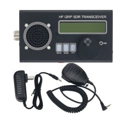
Ex Tax:$148.99NOTE:The latest version of the product appearance upgrade, performance improvement!!!Description:This is a shortwave QRP SSB/CW transceiver. It boasts..
$20.99
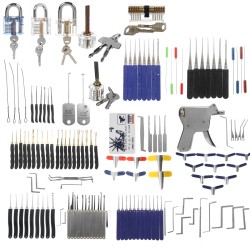
Ex Tax:$20.99Features:- Transparent lock: help you know the mechanism of the locks, useful for Locksmit to train and practice.- Friendly for beginners with instruc..
$4.99
Ex Tax:$4.99>>Please Contact us to Download the English User Manual<<
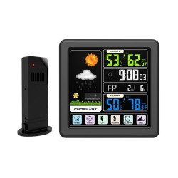
Main Functions: 1.Four-kind weather forecast: sunny, ..
$40.99
Ex Tax:$40.99>>Please Contact us to Download the English User Manual<<
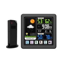
Main Functions: 1.Four-kind weather forecast: sunny, ..
$40.99
Ex Tax:$40.99Specification:
Name: Welding Ring Terminal
Type: Welding ring terminal white SST-S11 (5pcs) Welding ring terminal red SST-S21 (20pcs)..
$22.99
Ex Tax:$22.99 | ||

